
J_Appl_Mater_Eng 2021, 60(4), 99-108; doi:10.35995/jame60040008
The Influence of Inorganic Binder Type on Properties of Self-Hardening Moulding Sands Intended for the Ablation Casting Process
Sabina Puzio 1,* ,
Jadwiga Kamińska 1,
Michał Angrecki 1
and
Katarzyna Major-Gabryś 2
,
Jadwiga Kamińska 1,
Michał Angrecki 1
and
Katarzyna Major-Gabryś 2
,
Jadwiga Kamińska 1,
Michał Angrecki 1
and
Katarzyna Major-Gabryś 2
1
Łukasiewicz—Krakow Institute of Technology, 73 Zakopiańska Str., 30-418 Kraków, Poland; jadwiga.kaminska@kit.lukasiewicz.gov.pl (J.K.); michal.angrecki@kit.lukasiewicz.gov.pl (M.A.)
2
Faculty of Foundry Engineering, AGH University of Science and Technology, al. Mickiewicza 30, 30-059 Kraków, Poland; katmg@agh.edu.pl
*
Corresponding author: sabina.puzio@kit.lukasiewicz.gov.pl
How to cite: Puzio, S.; Kamińska, J.; Angrecki, M.; Major-Gabryś, K. The Influence of Inorganic Binder Type on Properties of Self-Hardening Moulding Sands Intended for the Ablation Casting Process. J. Appl. Mater. Eng. 2020, 60(4), 99–108, doi:10.35995/jame60040008.
Received: 11 December 2020 / Accepted: 26 March 2021 / Published: 31 March 2021
Abstract
:The aim of the present work is to compare the properties of self-hardening moulding sands based on inorganic binders based on sodium silicate of different modules, geopolymer binders and phosphate binders and to prove they can be used in the ablation casting process. Ablation casting is a process in which, directly after pouring the liquid alloy, the mould is sprayed with water until it is completely eroded and a finished, cooled casting is obtained. The use of proecological water-dilutable binder makes it possible to recover the sand matrix after drying the suspension that remains after the process. Moulding sands were prepared on the basis of four inorganic binders available on the market. For each of the moulding sands the bending strength was tested after 1, 2, 4 and 24 h of hardening. Then, the masses with optimum bending strength were selected and subjected to gas emissivity tests. A thermal analysis of moulding sands selected for testing was also carried out in order to determine the loss of mass during annealing. The susceptibility of moulds to erosion under the influence of ablative medium was also assessed by measuring the time of mould erosion. Tests showed the possibility of using self-hardening moulding sands based on inorganic binders for the ablation casting process of aluminium-silicon alloys.
Keywords:
innovative technologies; ablation casting; moulding sands; self-hardening sands; inorganic binders; hydrated sodium silicate; geopolymer binder; phosphate binder1. Introduction
Ablation casting is a relatively new method which is not used in Polish industry at the moment. It consists of casting in sand moulds that are intensely cooled with water during solidification until the mould completely erodes (Weiss et al. 2011). This process is applied to aluminium and magnesium alloys cast in disposable moulds and uses sand moulds with water-dilutable binders. The liquid alloy is cast in the sand mould and while it is still in the liquid state, the mould is sprayed with cooling medium (water) with nozzles until the mould is completely eroded. This allows the water to come into direct contact with the casting surface and avoids the occurrence of a shrinkage joint that occurs in classical casting methods, limiting heat transfer from the casting. A high-temperature gradient on the casting cross-section, especially in the case of thin-walled castings, facilitates the elimination of shrinkage porosity (Jordon and Wang 2011). The crystallisation under conditions of faster heat dissipation favours the formation of a fine-grained microstructure (Ananthanarayanan et al. 1992; Grassi et al. 2010). On the basis of the literature (Weiss et al. 2011), it can be concluded that the properties of such a casting can even be comparable or better than those of a pressure casting. The ablation casting process is used for castings made of nonferrous metal alloys with different wall thicknesses and complicated shapes made in sand moulds, in which a higher crystallisation time favours the formation of coarse-grained structures. In order to ensure beneficial changes in the structure, ablative washing of the sand mould should be applied immediately after pouring the mould with a liquid alloy. This method was patented in 2006 by Alotech. For the ablation casting technology, moulding sands based on small quantities of proecological water-dilutable inorganic binders are best. These moulding sands should be easily subjected to erosive action of the ablative medium. The most widely used binder is hydrated sodium silicate (waterglass), used for the first time in 1947 (Czech patent Petržela 1947, Major-Gabryś 2016). Moulding sands at that time were hardened with gaseous CO2. The development of loose self-hardening moulding sands with hydrated sodium silicate and liquid ester hardeners (in 1968) allowed reductions in the amount of binder used to approximately three parts of mass (thus improving the knock-out properties). In Poland, the most commonly used process is the floster process, in which Flodur type hardeners are used. Phosphate binders are characterised by good solubility in water. They are nontoxic and harmless to the environment and no organic compounds are used to harden them (Holtzer 2002). The moulding sands with these binders are characterised by good knock-out properties and reclamation. The basic binding components are phosphates, mainly orthophosphate aluminium(V). Powdered magnesium oxide MgO (Dobosz 2006) is mainly used as a hardener. Inorganic binders for the production of moulds and cores also include binders based on mineral polymers (geopolymers). The term “geopolymer” characterises a group of amorphous aluminosilicate materials. These were developed in France in the 1980s by Davidovits (Davidovits 1989). Self-hardening moulding sands can be hardened by means of esters, and an inorganic binding system has also been developed. An inorganic polymer based on silicon and aluminium was used here, which are formed by SiO4 and AlO4 tetraeder chains. As a result of the action of the hardener, the degree of polymerisation increases and a polymer with high binding capacity is formed. The course of gradual polymerisation of the binder results in a gradual increase in viscosity of the liquid and its transformation into a substance—i.e., polymer (Novotny 2005). The literature review has clearly shown the possibility of using various inorganic binders to make moulds for ablation casting technology. Our own research (Puzio et al. 2020) verified the possibility of using microwave-hardened moulding sand in technology, while hardening the sand by adding appropriate activators is a cheaper process, commonly used in industry, which does not require additional installation for hardening at the foundry. The aim of this work is to determine the influence of the type and quantity of inorganic binder used on the properties of self-hardening moulding sands intended for the ablation casting process.
2. Materials and Methods
In the framework of this work, strength tests of self-hardening moulding sands with four different inorganic binders and dedicated hardeners were performed. Subsequently, the amount of gases emitted from these moulding sands was determined, as were the characteristic temperatures of their thermal decomposition. The last stage of the research was the research determining the rate of mould erosion.
2.1. Bending Strength Tests of Moulding Sands
On the basis of our previous research, it has been established that the optimum strength of a mould intended for ablation casting, which will enable the transfer of metallostatic pressure of the liquid metal and ensure susceptibility to destructive action of the ablative medium, is 1.5–1.7 MPa (Kamińska et al. 2019). Chemical hardening of moulding sands is an economically profitable process. It also allows the obtention of optimum strength properties even with low binder contents in the moulding sand. This method of moulding sand hardening allows the obtention of castings with high dimensional accuracy and smoothness of the surface while eliminating casting defects, making it commonly used in industry. The following inorganic and water-dilutable binders intended for chemical hardening were tested:
- −
- waterglass R145;
- −
- waterglass R150;
- −
- geopolymer binder;
- −
- phosphate binder.
Binder datasheets are listed in Table 1.
Sibelco quartz sand classified according to the Polish standard PN-85/H-11001 as medium (main fraction 0.20/0.16/0.315) was used to prepare the moulding sands. In the case of waterglass, an ester hardener, trade name Flodur 3, was used. For the geopolymer binder, SA75 hardener recommended by the manufacturer was used. The phosphate binder was hardened with powdered magnesium oxide MgO.
The compositions of the tested moulding sands were as follows:
- −
- medium quartz sand: 100 parts by weight;
- −
- binders R145, R150, geopolymer and phosphate: 2.0, 2.5 and 3.0 parts by weight;
- −
- Flodur hardener: 8, 10 and 12%; SA75—10% relative to the binder quantity, MgO—5% relative to the binder quantity.
The methodology of preparing self-hardening moulding sands according to the literature (Lewandowski 1997) was as follows: initially the sand was mixed with the hardener for 90 s, and then the binder was added and mixed for another 90 s. From the prepared moulding sand, standard oblong mouldings were made for bending strength tests with dimensions of 22 × 22 × 172 mm. The LUZ-1 vibration compaction apparatus of Multiserw Morek company was used to compact the samples for a vibration time of 20 s and an amplitude of 1 mm. The bending strength was tested on Multiserw Morek’s LRu-2e type strength testing apparatus after the hardening times at ambient temperature for 1, 2, 4 and 24 h. Time measurements were taken for three samples and the arithmetic mean of the results that did not deviate from the mean by more than 10% was taken as the result.
2.2. Tests of Gas Emissivity of Moulding Sands
The determination of the amount of emitted gases (gas generating capacity) was performed in accordance with the industry standard BN-76/4024-05 (Polska Norma 1976). Measurements were carried out in an electric furnace with a measuring range of up to 1300 °C with a thermoregulator. A set of apparatus for determining the amount of emitted gases is shown in Figure 1.
The measurement consisted of placing the boat with a sample in an oven heated to 1000 °C. In total, 1 g of dried material was placed in the boat, which was subjected to a gas-forming test. The volume of the gas emitted was read every 5 s. The determination was stopped after 10 min or earlier if the volume of gases in the biuret did not increase within 1 min after the last reading.
For the gas-forming tests, moulding sands meeting the assumed value of Rgu bending strength and technological assumptions (ease of removing profiles from the apparatus, surface quality, etc.) were selected. Two samples from each material were subjected to gas-forming tests and the results were averaged.
2.3. Derivatographic Test
The thermal analysis of moulding sands selected for testing was carried out to determine the loss of mass during its annealing. The STA 449F3 Jupiter thermal analyser coupled with Aëolos QMS 403C was used for the TG-DTA-DSC-Cp test. During the thermal analysis, the samples were annealed to 1000 °C at a constant heating rate of 10 °C/min. Derivatographic tests allowed us to perform thermal differential and thermogravimetric analyses simultaneously. The changes occurring in the samples during their heating were recorded in the form of two curves:
- −
- TG—a graph indicating the change in weight of a sample with its temperature;
- −
- DTA—differential thermal curve (observation of thermal effects of changes—exo- and endothermal.
2.4. Mould Erosion Tests
The erosion tests were performed with the use of a device that could remove moulding sand from the casting and cool it, located in the Łukasiewicz—Krakow Institute of Technology and protected by the Polish patent number P.404518. The diagram of this device is shown in Figure 2.
The method of operation of the moulding sand removal device from the casting and its cooling according to the developed assumptions is as follows (markings according to Figure 2): The sand mould (14) was placed on the work table (2) extending outside the chamber (1). After pouring the mould (14), with controlled speed of rotation and vertical movement of the work table (2), it was inserted into the chamber (1). The work table (2), descending, introduced the mould (14) into the nozzle area (5). The mould was broken and the casting was cooled and solidified directionally. The suspension of the moulding sand in water flowed into the tank (6), where at the sieve (7) the moulding sand from the eroded mould (14) was deposited and water pumped (8) through the filter (9) was passed to the nozzles (5). After eroding the mould (14), the work table (2) was pulled out of the chamber (1) and the finished casting was removed (Dudek et al. 2014). An integral part of the device is a BOSCH high-pressure pump enabling the obtention of a liquid flow of 6.5 l/min at the maximum pressure of 12 MPa.
The following parameters were applied in tests:
- −
- number of revolutions—40 obr/min;
- −
- vertical feed—30 cm/min;
- −
- water pressure—12 MPa.
The mould for erosion testing was designed with future melting in mind. In order to enable even cooling during ablation casting, it was decided that the casting should have a round base. The designed tilt was to make it easier to take the model out of the mould after hardening and to knock out the finished casting from the metal mould. The diameter of the casting was chosen so that in future tests it could be freely used for structural and strength tests. The matrix, which enables the mould to be made in the technology of self-hardening moulding sands, was made of wood and covered with paint suitable for moulding sands. The casting diagram and the matrix are shown in Figure 3.
Moulds intended for erosion tests were prepared on the basis of four preselected compositions of self-hardening moulding sands. Each of the moulds was successively placed in the machine and the time in which it eroded from the moment the nozzles were switched on was measured.
3. Results and Discussion
The conducted Rgu bending strength tests showed that all tested masses have sufficient strength from the point of view of casting practice—i.e., they are able to transfer the metallostatic pressure of liquid metal. Moulding sands based on each of the selected binders allowed the tested samples to achieve the bending strength required for ablation casting technology (1.5–1.7 MPa). The surface quality of profiles made of self-hardening moulding sands is very satisfactory (it guarantees obtaining castings with good external surface quality). The results of tests for moulding sands containing an optimum percentage of hardener, which allows them to achieve the assumed bending strength after 24 h of hardening, are shown in Figure 4.
The gas emissivity tests showed that for all tested moulding sands the gas emissivity during sample annealing is low. This confirms the ecological nature of the process. The low gas emissivity of the moulding sands will have a positive effect on the quality of the external surfaces of the obtained castings. The composition of moulding sands and test results are presented in Table 2.
The total mass loss for all samples should not exceed 2 mg. Endothermal transformations occurred at similar temperatures (573, 571, 570 and 574 °C) for each of the tested moulding sands. These temperatures correspond to the polymorphic transformation of quartz at 575 °C. For all the tested binders, the biggest loss of mass took place at temperatures close to 100 °C, where the process of water evaporation from the moulding sand takes place. The total mass loss of the test specimens for almost all the binders took place at a temperature close to endothermal temperature—i.e., not exceeding 600 °C. A slight mass loss based on waterglass R145 at a temperature of about 780 °C may be caused by a higher content of ester hardener in the mass (10%). The results of derivatographic tests are presented in diagrams in Figure 5 and Figure 6.
On the basis of our previous research (Puzio et al. 2020), it was assumed that the mould for ablation casting should erode in no more than 300 s. Such a time allows for appropriate transformations to take place in the structure, which will allow the production of a casting with properties comparable to those of die casting technology. Based on the above assumptions, masses based on waterglass R150 and geopolymer binder should be eliminated from further tests. The shortest erosion time, amounting to 11 s, was characterised by a moulding sand based on the phosphate binder. This is due to the application of a hardener in the form of powdered MgO, which is highly hygroscopic and affects the rate of erosion of the mould. The results of the conducted tests are presented in Table 3.
4. Conclusions
On the basis of the literature data and our own research, the following conclusions have been drawn:
- −
- In a previous article (Puzio et al. 2020), microwave-hardened moulding sand tests were carried out. This article shows the possibility of achieving similar parameters for self-hardening sands and the possibility of using them in ablation casting technology. This will allow the costs of making moulds intended for this process to be reduced.
- −
- All the self-hardening moulding sands selected in this work achieved the assumed bending strength properties.
- −
- Not all the tested self-hardening moulding sands met the requirements for ablation casting moulding sands of Al alloys. Moulding sands based on waterglass R150 and geopolymer binder exceeded the assumed erosion time of moulds (>600 s) in the tests.
- −
- The process of mould erosion in ablation casting technology for moulding sands based on sodium waterglass R145 and chemically hardened phosphate binder takes place over a short time, which will allow high cooling rates of castings to be achieve and fine-grained structures to be obtained. For phosphate binder, this time did not exceed 11 s which is very favourable from the point of view of this technology.
- −
- The lowest gas emissivity is typical for moulding sands based on waterglass, whereas the gas emissivity of any of the tested moulding sands did not exceed 10 cm3/g.
- −
- The total weight loss of all samples did not exceed 2 mg, and the endothermic transformation took place at a temperature corresponding to the temperature of the polymorphic transformation of quartz (573, 571, 570, 574 °C). This proves that such a low content of inorganic binders to the masses does not cause any additional endothermic effects during the heating of the mass samples, which clearly confirms the ecological nature of the process.
The biggest advantage in terms of ablation casting technology is the moulds produced when using phosphate binder hardened with magnesium oxide.
Author Contributions
Conceptualization, S.P. and J.K.; Methodology, S.P. and J.K.; Validation, S.P., J.K., K.M.-G. and M.A.; Formal Analysis, S.P.; Investigation, J.K., S.P., and M.A.; Resources, S.P.; Writing—Original Draft Preparation, S.P. and J.K.; Writing—Review & Editing, S.P. and J.K.; Visualization, S.P.; Supervision, J.K.; Funding Acquisition, J.K.
Funding
This research was prepared as part of the projects financed from the Grant No. 1004/00 in 2020.
Conflicts of Interest
The authors declare no conflict of interest.
References
- Ananthanarayanan, L.; Samuel, F. H.; Gruzelski, J. Thermal analysis studies of the effect of cooling rate on the microstructure of 319 aluminium alloy. AFS Transactions 1992, 100, 383–91. [Google Scholar]
- Davidovits, J. Geopolymers: Inorganic, Polymeric New Materials. Journal of Thermal Analysis 1989, 37, 429–41. [Google Scholar] [CrossRef]
- Dobosz, S. Woda w masach formierskich i rdzeniowych; Wydawnictwo Naukowe AKAPIT: Kraków, 2006. (In Polish) [Google Scholar]
- Dudek, P.; Fajkiel, A.; Reguła, T.; Bochenek, J. Badania nad technologią odlewania ablacyjnego stopów aluminium/Research on ablation casting technology for aluminium alloys. Prace Instytutu Odlewnictwa/Transactions of the Foundry Research Institute 2014, 54(2), 23–35. [Google Scholar]
- Grassi, J.; Campbell, J.; Hartlieb, M.; Major, F. The Ablation Casting Process. Materials Science Forum 2010, 618–19, 591–94. [Google Scholar] [CrossRef]
- Holtzer, M. Kierunki rozwoju mas formierskich i rdzeniowych ze spoiwami nieorganicznymi w aspekcie zmniejszenia negatywnego oddziaływania na środowisko. Archiwum Odlewnictwa 2002, 2(3), 50–56. (In Polish) [Google Scholar]
- Jordon, J. B.; Wang, L. Monotonic and Cyclic Characterization of Five Different Casting Process on a Common Magnesium Alloy. Conference Proceedings: ASME 2011 International Manufacturing Science and Engineering Conference. Paper presented at ASME International Manufacturing Science and Engineering Conference, Corvallis, OR, USA, 13–17 June 2011; 2011. [Google Scholar]
- Kamińska, J.; Angrecki, M.; Puzio, S.; Hosadyna-Kondracka, M.; Major-Gabryś, K. The Use of Floster S Technology in Modified Ablation Casting of Aluminum Alloys. Archives of Foundry Engineering 2019, 19 (4), 81–86. [Google Scholar]
- Lewandowski, J. L. Tworzywa na formy odlewnicze; Wydawnictwo Naukowe AKAPIT: Kraków, 1997. (In Polish) [Google Scholar]
- Major-Gabryś, K. Odlewnicze masy formierskie i rdzeniowe przyjazne dla środowiska; Archives of Foundry Engineering: Katowice–Gliwice, 2016. (In Polish) [Google Scholar]
- Novotny, J. Masy samoutwardzalne z geopolimerowym systemem wiążącym. In Materiały VIII Konferencji Odlewniczej TECHNICAL 2005; 2005; pp. 111–118, (In Polish). Available online: https://docplayer.pl/5687044-Masy-samoutwardzalne-z-geopolimerowym-ukladem-wicym.html (accessed on 30 March 2021).
- Odlewnicze materiały i masy formierskie—Oznaczanie ilości wydzielonych gazów BN-76/4024-05. (In Polish)
- Puzio, S.; Kamińska, J.; Angrecki, M.; Major-Gabryś, K. Effect of the Type of Inorganic Binder on the Properties of Microwave-Hardened Moulding Sands for Ablation Casting Technology. Archives of Metallurgy and Materials 2020, 65(4), 1385–90. [Google Scholar]
- Sulfochem. Karta charakterystyki spoiwa Glifos CE; Sulfochem, 2015. (In Polish) [Google Scholar]
- Weiss, D.; Grassi, J.; Schultz, B.; Rohatgi, P. Testing the limits of ablation. Ablation of Hybrid Metal Matrix Composites. AFS Proceedings 2011. Available online: http://www.afsinc.org/files/mcdp/stories/magazine/webonly/11-057.pdf (accessed on 30 March 2021). [Google Scholar]
Figure 1.
A set of apparatus for determining the amount of gas emitted: 1—unpolished porcelain pipe for combustion, 2—electric furnace, 3—250 cm3 biuret with a three-way cock, 4—250 cm3 compensation tank, 5—device with 12 V electromagnet for inserting the boat, 6—porcelain pipe casing, 7—porcelain boat, 8—1000 °C temperature zone (BN-76/4024-05 1976) (Polska Norma 1976)
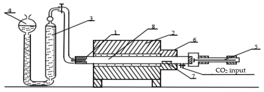
Figure 2.
Diagram of the device used for removal of moulding sand from the casting and cooling, where: 1—chamber, 2—movable work table, 3—lift, 4—drive system, 5—nozzles, 6—tank for flowing liquid cooling medium, 7—basket for collecting moulding sand from the broken mould, 8—pump, 9—filter, 10—high-pressure hoses for feeding liquid cooling medium to the nozzles, 11—distribution rail, 12—joints, 13—deflectors, 14—mould (Dudek et al. 2014)
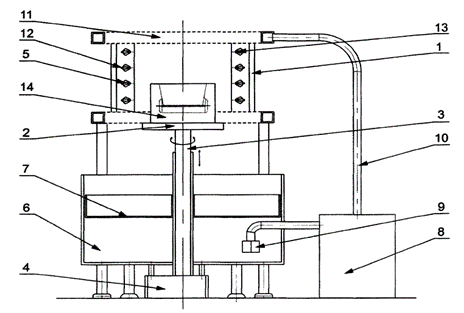
Figure 3.
Diagram of a test casting (a) and a moulding matrix for self-hardening moulding sands technology (b)
Figure 3.
Diagram of a test casting (a) and a moulding matrix for self-hardening moulding sands technology (b)
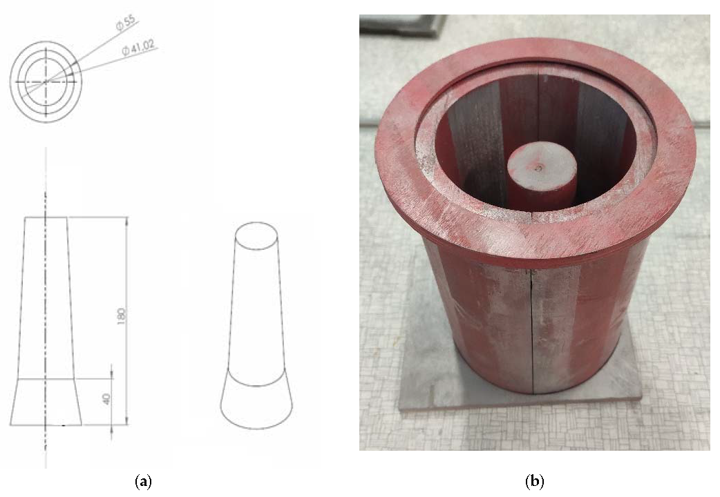
Figure 4.
Results of bending strength tests on self-hardening moulding sands after 24 h of hardening
Figure 4.
Results of bending strength tests on self-hardening moulding sands after 24 h of hardening
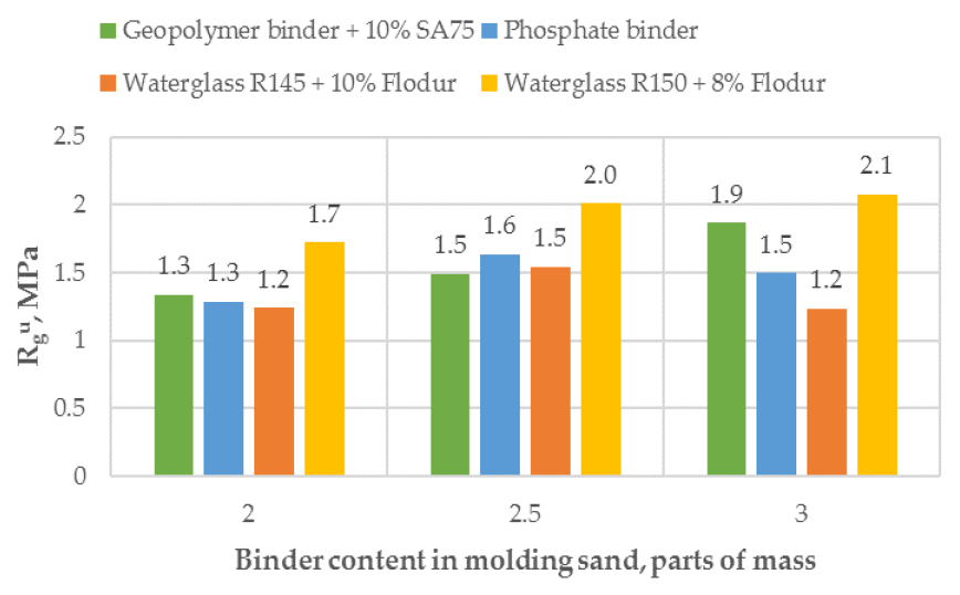
Figure 5.
Summary of differential DTA thermal curves
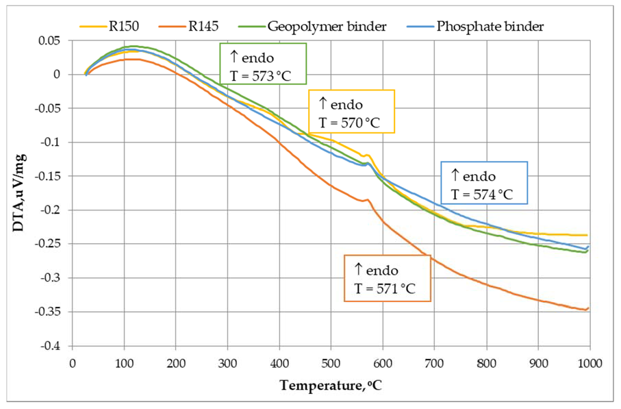
Figure 6.
Summary of mass losses TG
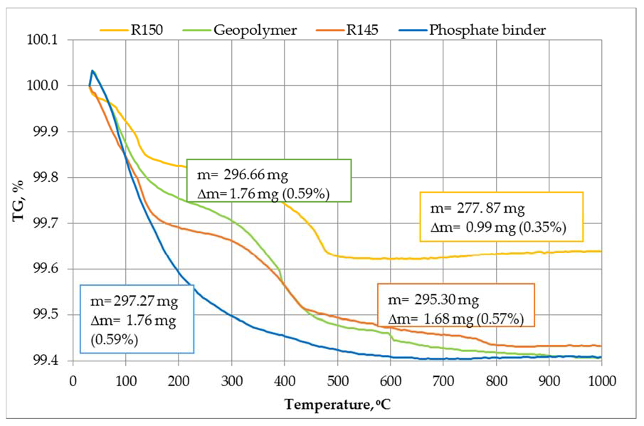

Table 1.
Binder datasheets: waterglass R145, waterglass R150, geopolymer (Z.Ch Rudniki S.A. 2017) and phosphate Glifos CE (Sulfochem 2015)
Table 1.
Binder datasheets: waterglass R145, waterglass R150, geopolymer (Z.Ch Rudniki S.A. 2017) and phosphate Glifos CE (Sulfochem 2015)
| Binder | Waterglass R145 | Waterglass R150 | Geopolymer Binder | Phosphate Binder |
|---|---|---|---|---|
| form | water solution | water solution | water solution | mixture |
| physical state | liquid | liquid | liquid | liquid |
| colour | transparent | transparent | milky | green |
| SiO2/Na2O (molar module) | 2.4–2.6 | 1.9–2.1 | 1.6–2.6 | – |
| pH (20 °C) | 11–13 | 11–13 | 11–13 | 3 |
| density (20 °C), g/cm3 | 1.45–1.48 | 1.50–1.53 | 1.51–1.53 | 1.6 |
| viscosity (25 °C), MPa·s | 20–40 | 20–40 | 25–35 | 6–8 |
Table 2.
Gas emissivity by selected moulding sand
| Moulding Sand Composition | Gas Emissivity, cm3/g |
|---|---|
| 5.5 |
| 6.5 |
| 10 |
| 10 |
Table 3.
Time it took for moulds to erode
| Binder | Erosion Time, s |
|---|---|
| sodium waterglass R150 | >600 |
| sodium waterglass R145 | 82 |
| Geopolymer binder | >600 |
| Phosphate binder (Glifos) | 11 |
© 2021 Open Access. This article is distributed under the terms of the Creative Commons Attribution-ShareAlike 3.0 (CC BY-SA 3.0).