
J_Appl_Mater_Eng 2020, 60(1), 3-11; doi:10.35995/jame60010001
Thermal Conductivity of Selected Ceramic Materials at a Transient Heat Flow
Jerzy Zych 1,* ,
Janusz Wróbel 2,
Jan Mocek 1
and
Marcin Myszka 1
,
Janusz Wróbel 2,
Jan Mocek 1
and
Marcin Myszka 1
,
Janusz Wróbel 2,
Jan Mocek 1
and
Marcin Myszka 1
1
Department of Moulding Materials, Mould Technology and Cast Non-Ferrous Metals, Faculty of Foundry Engineering, AGH University of Science and Technology, al. Mickiewicza 30, 30-059 Kraków, Poland; jmocek@agh.edu.pl (J.M.); mmyszka@agh.edu.pl (M.M.)
2
Exact Systems, ul. Ferdynanda Focha 53/5, 42-200 Częstochowa, Poland; fenix78@wp.pl
*
Corresponding author: jzych@agh.edu.pl
How to cite: Zych, J.; Wróbel, J.; Mocek, J.; Myszka, M. Thermal Conductivity of Selected Ceramic Materials at a Transient Heat Flow. J. Appl. Mater. Eng. 2020, 60(1), 3–11, doi:10.35995/jame60010001.
Received: 24 March 2020 / Accepted: 3 June 2020 / Published: 5 June 2020
Abstract
:In this paper, we present comparative investigations. We examined two kinds of ceramic materials used to produce bricks for isothermal cleading of the riser heads of middle and large steel castings. The ceramic materials were characterised by a low specific density (No. 1 − ρ = 0.854 g/cm3; No. 2 − ρ = 0.712 g/cm3). Thermal conductivity tests at a transient heat flow were performed by analysing the heating process of samples taken from the tested ceramic bricks, placed in a special mould in which metal was poured, and by recording the cooling process of the casting. The method proposed in this paper for the determination of samples’ thermo-physical properties is based on measuring the temperature field of the casting–sample system by means of thermocouples situated in various measuring points; it allows the direct investigation of cooling and solidification processes of metals in sand moulds. The heating process of the ceramic samples was analysed by measuring the temperature in five points situated at various distances from the heating surface (casting–sample surface). A large difference in the heating rates of samples of different materials was revealed in our comparative investigations, which indirectly indicated the materials’ heat abstraction ability from the casting surface. The ceramic material characterised by a lower density much slowly conducted heat and, therefore, appeared to be a better material for insulation cleading. At the depth of 40.0 mm, we measured differences in the heating degree corresponding to more than 190 °C. The aim of this comparative study was the evaluation of the suitability of porous insulating materials as cleading of riser heads used in the production of large steel castings.
Keywords:
riser heads; insulation cleading; porous ceramic bricks1. Introduction
The heat conduction properties of castings depend on their metallographic structure. During the heating process, crystallisation and cooling of metals and alloys influence the temperature of individual parts of a casting. They also influence heat accumulation in the metal and, therefore, the crystallisation of the whole casting (Kosowski 2003). For these reasons, knowing the thermo-physical properties of materials used for casting moulds, including all their elements such as various inserts they may contain, which come into direct contact with liquid metal, is very important. Similarly, the properties of materials used as insulation cleadings of riser heads are also critical, since they determine the heads’ efficiency. This is especially important for riser heads with large diameters, which are required to operate for long periods, a goal that can be achieved by slowing down the heat transfer from the head to the surroundings (mould).
In the case of riser heads with large diameters, the layers of the insulation cleading consist of ceramic bricks applied when the mould itself is being built. Exothermic or insulating cleadings produced by special companies are used for riser heads, and their dimensions are selected on the basis of their hot spot size, its placement, alloy kind, etc.
The heat flow from the casting to a sand mould is transient, similarly to the heat flow from the riser head through the ceramic material layers—applied as the insulation cleading—to the sand mould. Since the heat flux, at a randomly chosen moment and in a randomly selected heat exchange surface, is not constant, we can say that the heat flow has a random character. Enthalpy changes occur in all transient processes. These changes take place in materials releasing heat—in our case, liquid metal—as well as in materials receiving heat—in our case, the ceramic bricks in the riser head. The heat flux flowing from liquid metal to ceramic bricks depends on the temperature gradient at the contact surface between metal and brick and on the heat propagation and accumulation processes in the ceramic bricks. These, in turn, depend on the thermo-physical properties of the ceramic bricks’ material. These properties are determined by factors related to the material and to the state of the insulating bricks, which are mutually coupled (Szreniawski 1968). The thermal conductivity of materials used in the production of sand moulds has been studied in several scientific centres and presented in many papers (Banaszak 2006; Binczyk et al. 2006; Ignaszak 2003; Technical Cards of Tested Bricks 2018), and (Lewandowski 1991; Longa 1972; Longa et al. 1978; Pawłowski 1962; Szreniawski 1968; Zych et al. 2015).
2. Own Research
2.1. Subject and Methodology of the Investigations
The investigations presented in this paper are comparative. We examined two kinds of ceramic materials used to produce insulation layers for large riser heads of steel castings. An insulation layer of a riser head, consisting of ceramic bricks is shown in Figure 1.
The efficiency of the isothermal cleading depends on its thickness and on the thermal conductivity of the material of its individual segments (ceramic bricks). Commercial insulation materials contain information concerning their thermal conductivity; however, this information regards the use of bricks in ovens. How this same material behaves when in direct contact with liquid metal is not well known. Cast steel is poured into moulds at temperatures above 1500 °C, which greatly overheats the moulds’ elements, including the insulation layer consisting of porous ceramic bricks. Therefore, it was decided to estimate the insulation ability of the bricks under real conditions, i.e., at direct contact with a liquid metal. Thus, we assessed heat conductivity in the condition of a transient flow, which occurred in the casting mould after pouring the liquid metal. Thermal conductivity tests at a transient heat flow were based on analyses of both the heating process in the moulds’ layers—conducted, after pouring the liquid metal, on samples of the ceramic bricks used as insulation cleading of the riser heads—and the cooling process of the casting.
The thermo-physical properties of the casting–sample system were determined by measuring and recording its temperature field by means of thermocouples placed in various points, in line with direct investigation methods of cooling and solidification of metals in sand moulds. These methods are used for assessing the conductivity of materials used for moulds, including various kinds of moulding sands (Lewandowski 1991).
2.2. Tested Materials
The tests were conducted on samples of material taken directly from two different porous ceramic bricks used for building insulation cleadings of large rising heads of steel casts. Two cylindrical samples were cut out from a brick of each type. The investigated bricks consisted of mullite made with highly granular powders and ceramic of a high purity. They also contained small amounts of organic fillers, necessary in their production process. The bricks were sintered at high temperatures and, as indicated by their producers, had a very good thermal insulation ability.
The characteristic properties of the tested bricks, called light ceramic bricks, are presented in Table 1. In addition to their chemical composition, their heat conduction ability at three temperature values is reported, according to the producer’s material chart. The surface appearance of the tested materials is shown in Figure 2. Differences in bricks porosity are well visible.
2.3. Investigations at a Transient Heat Flow
Two samples of the tested ceramic materials were placed in a specially prepared measuring mould (Figure 3).
The ceramic samples had diameters and height of approximately 100 mm. Cylindrical ceramic samples were formed with the classic bentonite moulding sand, which was subjected to drying at 220 °C for 24 h. This treatment was performed to eliminate the influence on the measurement results of water evaporation from not dried moulding sand.
Four thermocouples were placed in each ceramic sample. They allowed to record the heating process of the tested material after liquid metal was poured in the mould. These thermocouples were placed in the samples at the depths of 6.0, 15.0, 25.0 and 40.0 mm from the casting surface. The casting cooling process was recorded for later comparisons in each measuring session by means of two properly placed thermocouples. The dimensions of the casting, made of grey cast iron, were 33 × 200 × 300 mm. Metal was poured in the mould at a temperature T ~1400 °C. A diagram of the system set-up is presented in Figure 4.
The temperature of the casting (plate) during cooling was measured in an immediate vicinity of the insert, which allowed us to assess, with a certain approximation, the influence of the heat abstraction ability of the ceramic moulding sand—used for making this insert—on the plate cooling time.
After performing the measurements, the heating time courses for each inserts made of ceramic bricks (Figure 5 and Figure 6) were plotted and compared.
By analysing the heating time courses of the two samples made of different materials (Figure 5 and Figure 6), we noticed that one of them (No. 2) reached higher temperatures then the other one (No. 1). This was especially evident when the measurements were performed further from the sample–casting surface (e.g., at a distance x = 40.0 mm). For sample No. 1, the temperature at this distance was near 370 °C, while for sample No. 2, the temperature reached a value near 410 °C. At a distance of 6.0 mm from the sample surface, the temperature was, in practice, the same for both tested materials (Figure 7). Differences started to appear at distances greater than 15.0 mm (Figure 8).
Differences in heating degree were significant and clearly seen deeper inside the samples. At a distance of 40.0 mm from the surface, they reached 60–70 °C. The inclination angle of the curve recording temperature vs. time was also significantly different (Figure 9). This behaviour of the insulation material is very important. A high heating temperature will affect the cooling and crystallisation processes of liquid alloys. An insulating material which heats up slowly insulates the riser head better than a fast-heating material and prolongs its cooling and feeding time, which altogether improves the feeding operation of the riser head.
In order to better present the differences in heat conductivity of the tested ceramic materials, we plotted the casting temperature vs. the temperature of the ceramic samples, as shown in Figure 10.
The heating time courses of the ceramic samples are presented as a function of the casting instantaneous temperature. The temperature of 1000 °C was selected for a comparative analysis. The samples’ temperature was determined in points at the greatest distance from the casting surface, i.e., x = 40.0 mm (Figure 10). The analysis results confirmed large differences in the heat conductivity of the two light ceramic bricks. Sample No. 1 heated up to 150 °C as the metal temperature decreased from 1400 to 1000 °C. Sample No. 2 heated up to app. 350 °C in the same time. An insulating material used for cleadings of riser heads should constitute a barrier for heat conductivity and should heat up slowly. On the basis of the obtained results for the two types of light ceramic bricks, it can be concluded that the material of sample No. 1 is better for insulating cleadings. The difference between the ability of these two materials to insulate riser heads is significant.
3. Conclusions
The determination of relative heat conductivity under conditions of transient heat flow is simple and allows the assessment and classification of materials used to make bricks for insulating cleadings of riser heads. The quality of these materials is important as it influences casting solidification, hot spots feeding by riser heads and eventual occurrence of axial porosities in castings at weak feeding. An insulating material that heats up slowly allows prolonging the solidification period of the riser head and, in fact, improving the operation of the riser head.
The performed tests allowed identifying the material that heated up more slowly and, therefore, is a better insulator for riser heads. The experiments also allowed us to determine the temperature difference of the tested samples at the same depth from the surface and at the same casting temperature. At the distance of 40.0 mm from the casting surface, this difference was approximately 190 °C, which indicates very different thermo-physical properties of the tested materials. These results and their implications should be discussed and interpreted considering previous studies and working hypotheses, in the broadest context as possible, also to provide future research directions.
Funding
This research was performed within the statute operations of AGH: Contract 16.16.170.654 Task 4.
Conflicts of Interest
The authors declare no conflict of interest.
References
- Banaszak, J. Wyznaczania współczynnika przewodzenia ciepła w materiałach porowatych. Materiały dydaktyczne. 2006. Available online: http://palmy.zameknet.pl/temperatury/dom%2002-21 (accessed on 15 December 2019).
- Binczyk, F.; Kulasa, J.; Przeliorz, R.; Smoliński, A. The definition of scanning calorimetric method the specific heat of the moulding sand. Archives of Foundry 2006, 6, 57–60. [Google Scholar]
- Ignaszak, Z. Substitute thermal conductivity coefficient for multi-component ceramic materials. Journal of Materials Processing Technology 2003, 143–44, 748–51. [Google Scholar] [CrossRef]
- Kosowski, A. Metaloznawstwo i obróbka cieplna stopów odlewniczych; Wydawnictwo Naukowe Akapit: Kraków, 2003; p. 30. [Google Scholar]
- Lewandowski, J. L. Tworzywa na formy odlewnicze; Wydawnictwo Naukowe Akapit: Kraków, 1991. [Google Scholar]
- Longa, W. Krzepnięcie odlewów w formach piaskowych; Wydawnictwo „Śląsk”: Katowice, 1972. [Google Scholar]
- Longa, W.; Urbanik, E.; Kapturkiewicz, W. Stygnięcie i krzepnięcie odlewów — Laboratorium; Skrypty Uczelniane AGH, Nr 623; Wydawnictwa AGH: Kraków, 1978. [Google Scholar]
- Pawłowski, Z. Wpływ składu masy formierskiej na jej przewodnictwo cieplne w wysokich temperaturach. Ph.D. thesis, AGH University of Science and Technology, Kraków, Poland, 1962. [Google Scholar]
- Szreniawski, J. Piaskowe formy odlewnicze; Wydawnictwa Naukowo-Techniczne: Warszawa, 1968. [Google Scholar]
- Technical Cards of Tested Bricks (names of producers hidden). 2018.
- Zych, J.; Mocek, J.; Snopkiewicz, T.; Jamrozowych, Ł. Przewodność cieplna mas formierskich ze spoiwami chemicznymi, próby jej zwiększenia. Archives of Metallurgy and Materials 2015, 60, 351–57. [Google Scholar] [CrossRef]
Figure 1.
Layer of ceramic bricks built as isothermal cleading of a riser head
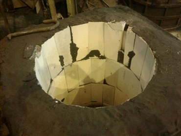
Figure 2.
Surface appearance of the tested ceramic bricks: (a) Sample No. 1; (b) Sample No. 2
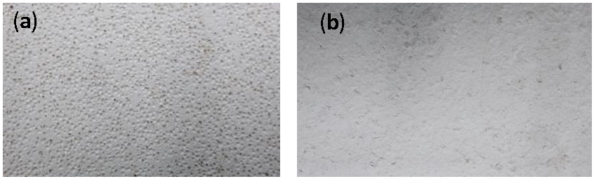
Figure 3.
Half section of the mould used to investigate heat conductivity containing two samples of the tested ceramic materials (light bricks)
Figure 3.
Half section of the mould used to investigate heat conductivity containing two samples of the tested ceramic materials (light bricks)
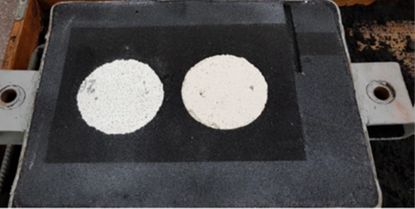
Figure 4.
Pictorial diagram of the system for measuring thermal conductivity directly in the mould; 1A, 1B – samples of the tested bricks, 2 – mould, 3 – inlet, 4 – thermocouple in the casting, 5 – plate casting, 6 – thermocouples in the bricks samples
Figure 4.
Pictorial diagram of the system for measuring thermal conductivity directly in the mould; 1A, 1B – samples of the tested bricks, 2 – mould, 3 – inlet, 4 – thermocouple in the casting, 5 – plate casting, 6 – thermocouples in the bricks samples
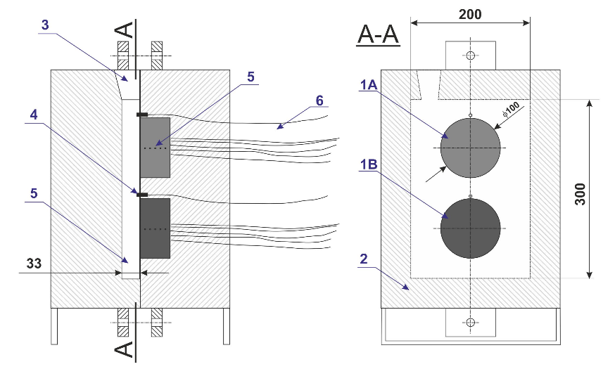
Figure 5.
Heating time course for the ceramic brick insert indicated as Sample No. 1
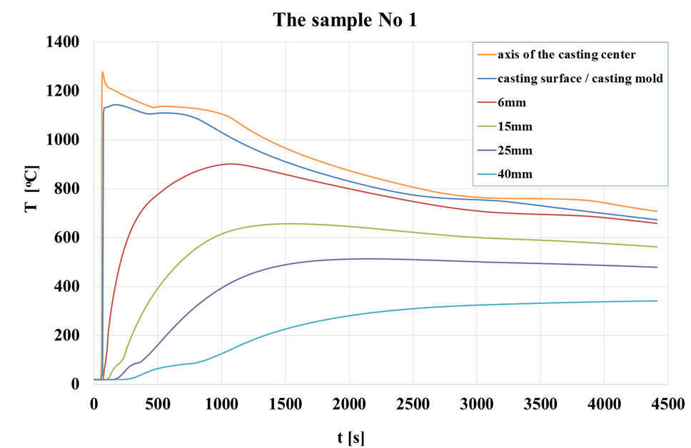
Figure 6.
Heating time course for the ceramic brick insert indicated as Sample No. 2
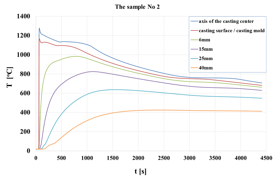
Figure 7.
Heating time courses of brick samples at a distance of 6.0 mm from the sample–casting surface
Figure 7.
Heating time courses of brick samples at a distance of 6.0 mm from the sample–casting surface
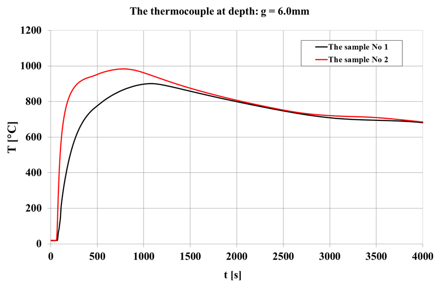
Figure 8.
Heating time courses of brick samples at a distance of 15.0 mm from the sample–casting surface
Figure 8.
Heating time courses of brick samples at a distance of 15.0 mm from the sample–casting surface
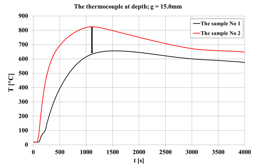
Figure 9.
Heating time courses of brick samples at a distance of 40.0 mm from the sample–casting surface
Figure 9.
Heating time courses of brick samples at a distance of 40.0 mm from the sample–casting surface
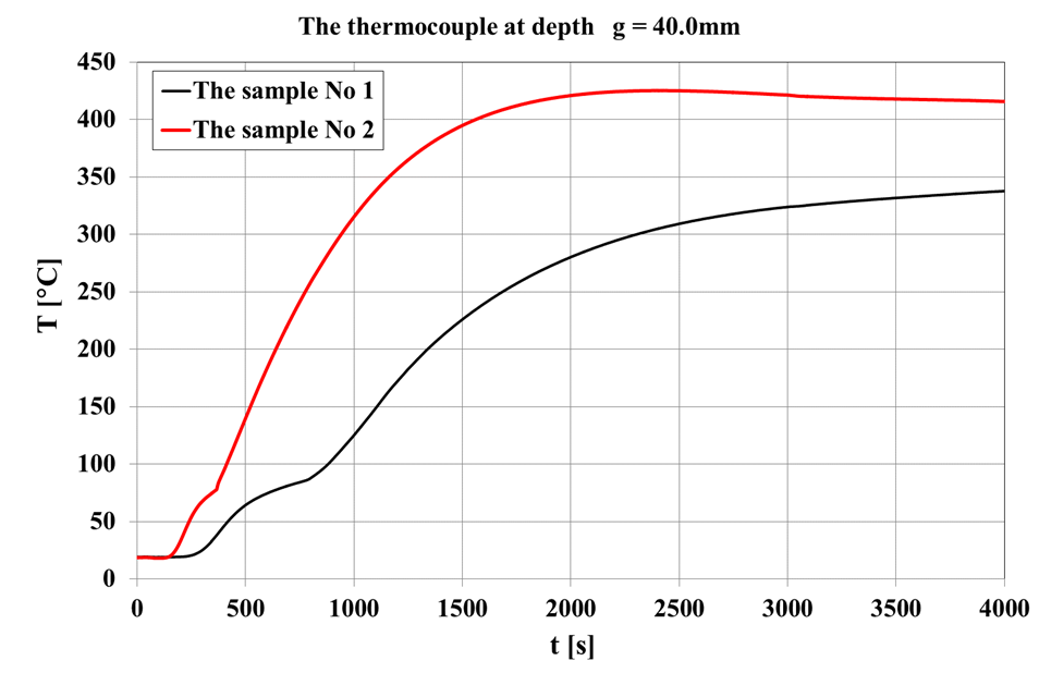
Figure 10.
Comparison of the temperatures of samples No. 1 and No. 2 at a distance of 40.0 mm from the casting face; the dotted vertical line highlights the difference at a casting temperature T = 1000 °C
Figure 10.
Comparison of the temperatures of samples No. 1 and No. 2 at a distance of 40.0 mm from the casting face; the dotted vertical line highlights the difference at a casting temperature T = 1000 °C
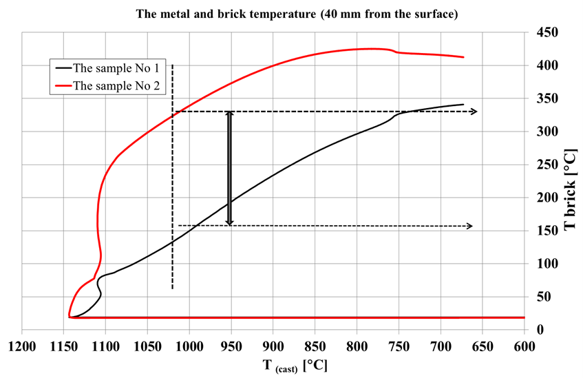

Table 1.
Physicochemical properties of the tested ceramic materials (Technical Cards of Tested Bricks 2018)
Table 1.
Physicochemical properties of the tested ceramic materials (Technical Cards of Tested Bricks 2018)
| Sample | Properties | Chemical composition | Thermal conductivity coefficient λ [W/M·K] | ||||||
|---|---|---|---|---|---|---|---|---|---|
| ρ [g/cm3] | Rc [MPa] | Al2O3 [%] | Fe2O3 [%] | SiO2 [%] | CaO [%] | T = 200 °C | T = 600 °C | T = 1000 °C | |
| No. 1 | 0.85436 | 1.0 | 35.0 | 2.0 | 56.0 | 0.4 | 0.17 | 0.21 | 0.28 |
| No. 2 | 0.71252 | 1.5 | >51 | <0.8 | 39.1 | 0.1 | 0.25 | 0.29 | 0.34 |
© 2020 Open Access. This article is distributed under the terms of the Creative Commons Attribution-ShareAlike 3.0 (CC BY-SA 3.0).